

Industrial Air Conditioning Factory: Engineering Reliable Climate Control Systems for Large-Scale Facilities
2026-10-16
When a single degree of temperature swing can shut down a production line or corrupt sensitive equipment, you stop thinking of HVAC as a commodity. That's the mindset behind Tongbaote—an industrial air conditioning factory that designs and builds climate control systems for the largest, most demanding facilities. In this post, we'll look at what actually makes these systems reliable.
Specifying Cooling Around Real Loads, Not Catalog Numbers
Data center cooling has long been trapped in a catalog-driven mindset, where engineers select chillers, CRAC units, or AHUs based on nominal capacity badges rather than the actual heat load profile. This practice leads to mismatched systems that either overcool, wasting energy, or undercool, risking downtime. Specifying cooling around real loads begins with accurately characterizing the IT equipment's power draw, including its variability throughout the day and across seasons. Instead of relying on nameplate ratings—which often overstate consumption by 30 to 50 percent—designers should use measured or simulated load data from actual deployments. This shift from catalog numbers to real thermal behavior allows cooling infrastructure to be right-sized, avoiding both capital overspend and chronic inefficiency.
The core of this approach lies in mapping the spatial and temporal distribution of heat within the facility. Rather than assuming a uniform load density based on a generic server type, engineers must account for the clustering of high-density racks, the presence of storage arrays with lower power draws, and the periodic bursts from batch processing or AI training jobs. Such granular load profiles feed into computational fluid dynamics models and room-level controls, enabling cooling delivery to follow the heat instead of blanketing the entire space. For example, a row of GPUs running at 80 percent utilization may require targeted liquid cooling, while adjacent networking gear can be served by simple airflow management. This precision not only reduces total cooling energy but also extends equipment life by maintaining tighter temperature bands.
Transitioning to real-load specification also demands a different collaboration model among stakeholders. Facility teams, IT architects, and cooling vendors need to share transient load data and operational schedules early in the design phase. Instead of asking “What size chiller do I need per catalog?”, the conversation becomes “What is the peak and average heat rejection for this specific workload, and how does it shift over time?”. Tools like digital twins and continuous commissioning then keep the system aligned as loads evolve. The payoff is a cooling infrastructure that behaves like a tailored garment rather than an off-the-rack suit—minor adjustments, no wasted capacity, and resilience built on observed reality rather than manufacturer spec sheets.
What Happens on the Factory Floor Before a Chiller Gets Its Nameplate
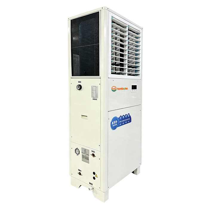
Long before a chiller earns its nameplate, the assembly floor hums with a sequence of steps that most customers never see. Technicians start by pressure-testing the evaporator and condenser shells, filling them with nitrogen to catch microscopic leaks that would spell trouble later. The compressor—often a screw or scroll type—gets bolted to its base with laser-aligned mounts, because even a fraction of a millimeter off can translate into vibration and premature bearing wear. Wiring harnesses are routed through protective conduits, and every connection is torqued to a spec sheet pinned at the workstation.
Once the refrigerant circuit is closed, the unit goes through a vacuum pull-down that can take hours. Moisture is the enemy here; any residual water vapor will mix with the oil and form acids that eat away at motor windings. Factory techs use a micron gauge to confirm the system holds below 500 microns, then charge it with the exact refrigerant weight listed on the engineering print. After that, the chiller is connected to a test stand where simulated load conditions push it through part-load and full-load scenarios. Temperatures, pressures, and power draw are logged minute by minute, and any deviation beyond a tight tolerance sends the machine back for rework.
Only after passing a final sound test and a visual inspection of every braze joint does the nameplate get riveted on. That small metal tag carries the model number, serial, refrigerant type, and electrical ratings—but it also signals that a particular chiller survived the gauntlet of checks designed to catch defects before they leave the plant. For the people on the floor, the nameplate is less a label and more a signature of workmanship.
Leak Checks, Vibration Sweeps, and the Hidden Work Behind Reliability
Walk through any plant after hours and you'll hear it—the quiet hiss of a fitting that isn't quite tight, the faint rattle from a pump base that shifted just enough to matter. These aren't the failures that make headlines. They're the slow leaks and subtle harmonics that eat away at uptime while everyone's focused on the big, obvious breakdowns.
A proper leak check isn't just running a soapy brush over a joint. It's knowing which seals fail first under thermal cycling, which flange faces were torqued by someone in a hurry, and which ultrasonic signatures signal a pinhole before it becomes a spray. Vibration sweeps follow the same logic: measure the baseline, map the resonance points, then track the drift. A 0.1 mm/s change can mean a bearing is losing its preload, a coupling is misaligned, or a foundation bolt has backed off half a turn.
The hidden work is exactly that—hidden. It's the 3 a.m. walk-down with a flashlight and a listening stick. It's logging readings that don't trip any alarms yet but sit just outside the expected envelope. It's the technician who notices the condensate drip that wasn't there last week, or the gearbox that feels warmer than it did in spring. Reliability isn't built in a boardroom or a reliability-centered maintenance spreadsheet. It's built in these small, repeated acts of attention that never make it into the maintenance report—but keep the whole system from drifting into the failure curve.
The Test Chamber That Runs Units at 55°C Ambient and -30°C Cold Start
In this chamber, every unit faces a swing from -30°C cold starts to sustained 55°C ambient operation. The cold start isn't just a temperature drop; it's a full thermal shock that exposes weak solder joints, brittle seals, and sluggish power delivery before the system even warms up. That's the point.
The 55°C ambient side is equally unforgiving. Cooling paths that look fine at room temperature start to choke, and components rated for typical indoor use drift out of spec. By running the unit under load in that heat, the chamber reveals whether the thermal design actually holds or just survives on paper.
Together these two extremes create a much harsher picture than standard cycling tests. A unit that passes here has proven it can wake up frozen and then keep working while the surrounding air stays hot enough to make the enclosure painful to touch.
Scaling from a Single Rooftop Unit to a Campus-Wide Cooling Network
The journey from cooling a single building with a rooftop unit to orchestrating a campus-wide chilled water loop rarely follows a straight line. Early on, the easiest wins come from standardizing equipment protocols and data formats across the handful of machines you already own. Once two or three buildings feed their operational data into the same dashboard, the conversation shifts from fixing individual compressors to noticing patterns: a pump running needlessly at night, a cooling tower fan cycling too aggressively on mild days, or a chiller plant that could be staged more intelligently.
Expanding that visibility across an entire campus forces a different kind of inventory. You start to treat cooling capacity not as a collection of independent assets, but as a portfolio with shared reserve margins and demand curves. A hospital, a lab, and a residence hall may have wildly different load profiles, yet their peaks often don't coincide. By connecting them through a common hydraulic and control layer, you unlock the ability to shift load from one plant to another, pre-cool buildings with high thermal mass, or even let a small packaged unit borrow capacity from the central plant during a heat wave.
The real scaling challenge isn't the pipework or the sensors; it's the governance. Decisions that used to live with a single facility manager now involve multiple stakeholders with conflicting priorities. Setting up clear ownership of the network, agreeing on how to allocate costs when one building exports chilled water to another, and building trust in automated optimization all matter more than the hardware. Once those pieces fall into place, the campus network stops being a retrofit project and becomes an operating strategy that can absorb new buildings without a proportional jump in operational complexity.
Designing for the Technician: Clear Access and Predictable Spares
The servicing layout begins with a simple promise: if a technician has to fight the machine, the design has already failed. Panels lift away on gas struts, filters slide out without tools, and every connection point is visible from a standing height. There is no hidden fastener behind a wiring loom, no drain plug placed above a crossmember. The access paths follow the natural sequence of the task: drain, remove, replace, test. In the field, that means a belt swap takes minutes, not an afternoon of disassembly.
Predictable spares go hand in hand with that access. We avoid one-off components where a standard bearing or a common seal will do the same job. Part numbers are grouped by function, not by model year, so a pump rebuild kit from five years ago still fits the unit shipping today. Fasteners are reduced to a handful of sizes, and every wear item is stocked at regional hubs rather than shipped from a single factory. The result is less guessing, fewer emergency orders, and a van that carries what it actually needs.
Technicians also get real guidance, not a wall of generic warnings. Torque values are printed next to the bolt they belong to, not buried in an appendix. The service manual follows the same sequence as the machine: open, inspect, replace, close. And when a spare is replaced, the new part has a QR code that pulls up its install notes and the last revision date. That closes the loop between the bench and the field, so a change made on the line today is understood in the workshop tomorrow.
FAQ
We mainly handle manufacturing plants, data centers, pharmaceutical cleanrooms, and large logistics hubs. Each project starts with a site load assessment so the cooling capacity matches actual heat rejection from machinery and occupancy, not just floor area.
Reliability comes from redundant compressor circuits, industrial-grade controls, and remote performance monitoring. We also run accelerated life tests on critical components before shipping, which catches early failures that standard factory tests miss.
Yes. We offer coated coils, sealed electrical compartments, and high-static fans for dirty or aggressive atmospheres. In one chemical processing project, we used epoxy-coated evaporator fins and stainless steel drain pans to prevent corrosion-related downtime.
Custom engineering is our default for large facilities. We adjust airflow, cooling capacity, footprint, and control interfaces to match the building management system. A recent automotive plant required units with extended casing to fit between existing roof trusses, which we designed and verified within three weeks.
We use variable-speed compressors, electronically commutated fans, and free cooling options for low ambient conditions. The energy management logic prioritizes partial-load efficiency, which is where large facilities spend most of their operating hours.
We have field service engineers for commissioning, preventive maintenance, and emergency repairs. Spare parts are stocked in regional depots, and critical control boards can be shipped within 24 hours. We also offer training for on-site maintenance teams so they can handle routine filter changes and coil cleaning safely.
Each unit undergoes a full-load test in our climate chamber, including airflow, cooling capacity, and control response. For large projects, we can invite the client to witness the test or stream the data live. Any deviation above 3% from the rated curve triggers a rework order.
We focus on process cooling and humidity control, not just comfort. That means tighter temperature tolerances, heavier casings, and components sized for continuous duty. Our engineering team also stays involved after installation to fine-tune setpoints and airflow distribution, which reduces hot spots in large open production halls.
Conclusion
In this industrial air conditioning factory, the focus stays on engineering climate control systems that match the actual thermal loads of large-scale facilities rather than relying on catalog numbers. Teams begin by mapping real heat gains, occupancy patterns, and process loads, then translate those into cooling duties that keep equipment from being oversized or underfed. Before a chiller earns its nameplate, it passes through a sequence of factory-floor steps that often go unseen: leak checks on every refrigerant circuit, vibration sweeps across compressor and fan assemblies, and torque verification on critical joints. These hidden tasks are what separate a unit that works on day one from one that keeps working for years.
The factory's test chamber pushes machines to 55°C ambient and demands cold starts at -30°C, so field surprises shrink. Systems scale from a single rooftop unit to a campus-wide cooling network by reusing proven modules and control logic, not by redesigning from scratch. Maintenance is designed in from the start, with clear access panels, labeled components, and predictable spare parts so technicians spend less time guessing. The result is climate control that feels ordinary on the outside but is deliberately engineered underneath: sized to actual loads, proven under stress, and built to be serviced without heroics.
Contact Us
Contact Person: Wanshu Chen
Email: [email protected]
Tel/WhatsApp: +86-13662871206
Website: https://www.mbcee.com